The initial configuration of the PCC includes:
1. Setting a 4-digit password for SMS commands.
2. IP address.
3. Gateway.
4. Mask of network.
5. Voltage correction on the voltage sensor.
6. Turn on / off the ability to control via SMS commands.
7. Sending logs to an external server on the Internet.
8. Inversion on channels ~ 220 /110
9. Turn on inversion on additional relay channels.
10. Turn on debug mode on the PCC with the subsequent output of internal logs.

You need to start setting up the PCC with its configuration. The configurator can be downloaded below.
Before proceeding with the configuration, you must connect the PCC via a USB cable to the computer. To do this, select the left USB connector on the Arduino board, as shown in the photo below.

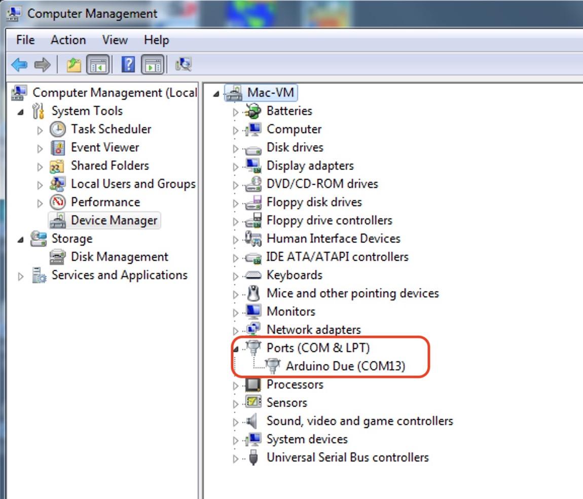
After a physical connection, you need to make sure that the computer "sees" the PCC. In the device control panel, you should see something similar to what is shown in the screenshot below. If your computer ask you the drivers for connection, please download its below, unzip and install.
Then select the appropriate port in the configurator and click the Connect button.
Next, you need to read the current configuration of the PCC by clicking the Read button. The values recorded in the PCC memory will appear in all the windows of the configurator.
To change the configuration, you need to make new (or correct the current) values, and then click the Write button. It should be noted that the IP, gateway and network mask values must be 3 digits !!! Namely, the value 0 must be written as - 000, the value - 1, as - 001 etc.